Greetings. The fuzz kit is ready. Here is the final info (and ordering info).
-For my simplicity and for keeping the price low enough, the FuzzKit includes the following:
+Fuzzkit PCB
+Potentiometer, Battery clip, audio jacks
+Components to build an Electra Distortion
+Knob (of my choice)
+length of wire
+length of solder
(You provide a soldering iron, wire snippers, and a drill for mounting it in something)
(For a couple reasons I will not be selling the kit with components for the Bazz Fuss. I also opted to include a knob instead of a sticker)
Build instructions will be posted in the next day or two (I just took all the photos and need to write it all out). The instructions will tell you how to assemble the kit so that you may house it in any possible item you may fit it into. I built the sample kit in an old salsa jar. Due to lack of time I will not be writing instructions on how to wire it up for bypass, powerjack, or led, but there is plenty of info for the enterprising DIY'er at generalguitargadgets.com, beavisaudio.com, or other sources. This thread will remain open so that anyone may ask questions for help or mods to their kit. I am here to help!
PRE-ORDER INFO
The preorder price for the kit is $11 plus shipping. Shipping in the USA will be $2, anywhere outside the states will be $3. If you ordered a Clean Chan/Dirty Chan limited pedal, and you order a fuzzkit, I will ship it to you for free inside your CC/DC box.
If you are interested in buying JUST a PCB, they will be $7 INCLUDING shipping, anywhere, or $13 for two, or $18 for 3.
To pre-order send payment by paypal to eric@letsgocoyote.com
Examples
I ordered a CC/DC pedal > send $11
I am in the USA > send $13
I am out of the states > send $14
I want PCBS > sendd $7, or $13, or $18
I want multiple kits > I can ship two kits for the same price, so $24 tota for two in the USA, $25 for two full kits outside the USA
Pre-Orders accepted until May 14. Estimated ship date is on or before May 31st.
Price per kit after May 14th is $13 plus shipping
FuzzKit Pre-Orders and Instructions Thread!
Moderator: letsgocoyote
-
letsgocoyote

- FAMOUS

- Posts: 1305
- Joined: Mon Oct 01, 2007 4:07 pm
-
letsgocoyote
- FAMOUS
- Posts: 1305
- Joined: Mon Oct 01, 2007 4:07 pm
Re: FuzzKit Pre-Orders and Instructions Thread!
FUZZKIT INSTRUCTIONS!!
You got your Fuzz Kit in the mail. Awesome. You need some tools! You need:
-A soldering iron. You can get a cheap 30w soldering iron form Radio Shack for about $7-10 I believe. The tips on these get corroded after several projects, but for a beginner it's fine as it is a low investment for an iron.
-Some small snipping pliers for stripping wire and trimming component leads. In a pinch you might be able to use scissors or something... but i might not work well. You can probably find a cheap pair of wire snippers at a thrift store, dollar store, or if you have a Harbor Freight in your town they have tons of cheap cheap tools for sale (also kinda cheap quality... but as a beginner a low investment is ok until you know you are serious).
-optionally a drill and some bits so you can put it in some kind of enclosure.
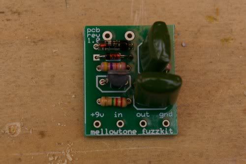
So here is the kit:
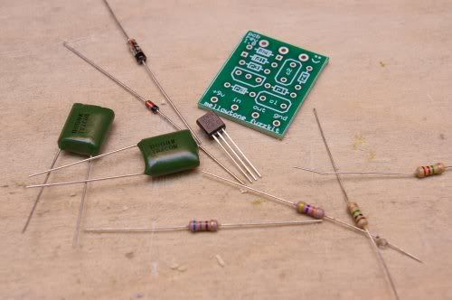
You get:
-PCB
-2n3904 transistor
-(2) .1uf capacitors <your capacitors might vary from those pictured
-1n914 Silicon Diode
-1n34a Germanium Diode <the germaniums I included in the kits I sent out look different than in the picture, and look very close to the silicon diode. to tell them apart, the silicon diode IS marked with 1n914, albeit very small letters, and the germanium is blank except for the stripe>
-2.2meg resistor (red-red-green-[gold])
-1meg resistor (brown-black-green-[gold])
-47k resistor (yellow-purple-orange-[gold])
-680ohm resistor (blue-grey-brown-[gold])
-stereo input jack (its a mono pedal, but the stereo jack gives you an extra tab to turn the battery on, you'll see)
-mono output jack
-battery clip.
You will need a few skills to build this. First you need to be able to sort out the resistors, so you need to be able to read the resistor color codes. Resistors have a tolerance band, in this case of these carbon film resistors, its gold. you start reading the colors opposite of this band. heres a link with more info, but i told you the colors of each resistor above to make it easy:
http://www.bcdxc.org/resistor_color_codes.htm
You also need to know how to properly solder! Here's a link on instructables, but you can find more links out on google:
http://www.instructables.com/id/How-to-solder/
Good soldering is key otherwise you might end up with bad cold joints, or if you glob a bunch on you might acidentally connect to spots that weren't intended to be connected.
Now, lets get down to business. In case you don't know, we are building the Electra Distortion... although it is possible to build other things on this PCB...
Heres the schematic as you find commonly on the web:

You may notice there is no 1meg resistor on the common schematic. Really it is optional, but I added to the PCB because the 1meg resistor is used as what is known as a 'pulldown resistor'. What it basically does is gives the input capacitor a path to continuely leak out of so that when you switch the pedal on it doesnt make a 'pop', or at least not as loud of a one. Now, as we are only building this as simple hardwired effect, it really has no purpose, but since I know some of you will house this and wire it up with a footswitch, I put it on there.
So lets talk about the circuit. The guitar signal goes in to the first .1uf capacitor, where it is then amplified by the 2n3904 transistor. The 2.2m and 47k resistors control the bias of the transistor, and the 680 resistor controls the gain. So varying the value of the 680 ohm resistor can change the gain. Also changing the value of the 47k resistor control the gain. Theres otherways to control the gain as well. The signal then goes out through the second .1uf capacitor. It is then clipped by the antiparralel diodes which provide assymetrical clipping. The 100k pot is a voltage divider which controls volume.
It's time to populate the board
1. RESISTORS
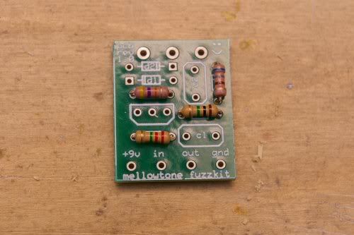
We solder in the resistors. R1 is 1meg, R2 is 2.2meg, R3 is 47k, and R4 is the 680ohm resistor. Simply bend the component leads at 90 degree angles and slip them through the holes. You can actually all stick them in at once, flip it over so its laying upside down, and since they are all the same size it will lay pretty flat so you can solder them all at once. Or you can do one at a time, your choice. Make sure to clip the leads after you solder any part!
2. DIODES
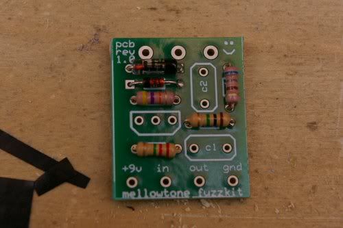
D1 is the 1n914 and D2 is the 1n34a. You must orient the diodes with the stripe (cathode) so that it matches the stripe on the white silkscreen layer on the PCB. Also, take more care when bending the leads on these diodes. Bend them gingerly, because the diodes are made of glass and you don't want to break them! Solder em in! We did the diodes second because they are basically the same size as the resistors so when you flip it over to sold it will still lay pretty flat.
3. CAPACITORS
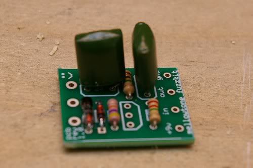
Both capacitors are the same value, and the ones in this circuit aren't polarized (some types of capacitors liek electrolytics are polarized and have to go a certan way) so you can just stick em in. You may wish to bend the leads slightly after you put them throughthe holes to hold it in place while you solder.
4. TRANSISTOR
Last is the heart of the little beast... the transistor. It goes in a certain way becauce each of the three legs is something different- the base, collector, and emitter. Older transistors were round and metal with a tab to help you know. Modern to-92 transistors are semicircles. Orient it in the PCB so that large flat face matches that of the white silkscreen shape on the PCB. We solder the transistor last because they are the most sensitive to heat, so doing it last exposes it to less heat from soldering other things. ALthough modern silicon transistors arent as sensitive.
5. WIRES!
You are provided with a battery clip and a length of wire. Cut the wire into 4 equal pieces (should end up abotu 6 inches each). You will set one wire aside but we need three now. There are four holes in the bottom of the pcb, plainly labelled for your convenience: 9v+, In, Out, Ground. The 9v positive connection is provided by the battery clip, so solder the red lead of the battery clip in this hole. Strip the ends of three of your wires and solder these in the other holes and then we can make the appropriate connections later.
6. POT!
We are using a PCB mount pot which is super convenient. However, because the the pot is metal and will be touching the bottom of the PCB, it could short things out! So all we need to do is put a piece of tape, a sticker, glue a piece of cardboard, anything thin and non-conductive, to completely cover the back of the pot casing. Then we won't short anything. After that, just stick the pot through the three large holes as shown, and solder it in and make sure to use plenty of solder here so that the joints are sturdy. If the legs of your pot come bent up a little just straighten em out so it fits.
7. JACKSSSSSSSSSSSSS
First jack we will solder will be the output (mono, 2 tab) jack:
This jack has two tabs. If you orient the jack as pictured, the upper tab is the sleeve/ground, and the lower tab is called the tip. Solder the Out wire from the PCB to the lower tip tab. (of course make sure you strip the end first!) Use plenty of solder. Next, we take that spare fourth wire we set aside, and we solder that to the upper ground tab. I'll explain why in a minute.
Next is the input (stereo, 3 tabs) jack:
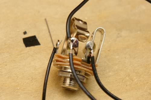
This one is slightly more complicated. If you have the jack oriented as pictured, then this jack also has a tip (rightmost tab) and a sleeve (center tab), but it also has another part called the Ring (leftmost tab). These jacks are used for stereo signals, or in the case of fx pedals they are commonly used for another purpose. It's difficult for me to explain, but here goes: a stereo plug (cable) is divided into three sections that each individually touch the sleeve, ring, and tip, but a mono plug only has two sections which are made to touch sleeve and tip. When you put a mono plug into a stereo jack, the sleeve part of the plug touches the sleeve of the jack AND the ring of the jack. So in a pedal, if nothing is plugged into the input jack, then the ring and the sleeve arent connected, but if you put your guitar cable in the ring and sleeve are now physically connected. This is useful because: If we connect the ground of the battery to the ring it doesnt complete the whole electrical circuit until the ring is connected to the sleeve. So the battery is only ON if you plug your cable into the input jack. Unplug and its OFF and not killing your battery. So there.
LETS SOLDER.
Solder the black lead of the battery clip to the RING (left tab in picture). Solder the OUT wire to the TIP (right tab). Finally, heres where its tricky.... put both the Ground wire from the PCB and the spare wire we soldered to the output (mono) jack to the sleeve of the input jack. Both of them solder to that middle tab. Reason? When you build a pedal the sleeves (ground) are both connected to the metal chassis and so both are grounded togehter like they need to be. But since this is a diy thing and you might end up putting this in a less than conductive enclosure that might not happen, so that spare wire is just insurance that all our grounds are properly connected. In your signal chain all your tips are the hot signal and are broken up by various effects and such, but ALLL the grounds, from your guitar to pedals to amp, etc. are connected one way or the other.
Anyhow, it should look like this:
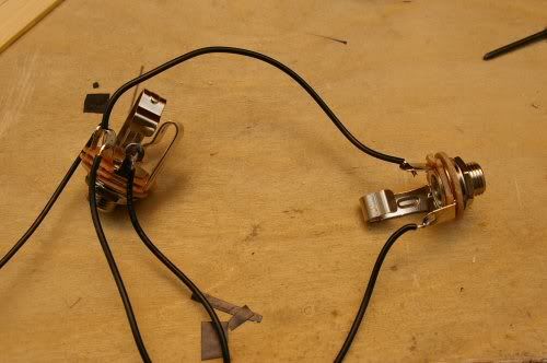
Ok, it should be all put together. You can hook up a 9volt battery, plug her in (make sure to plug your guitar into the right jack and your amp into the correct jack of course) and test it out. Either it works, or something went wrong and you need help. I promise to help you.
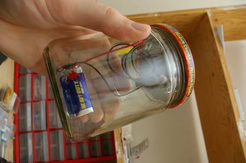
But supposing it works, then you can stick it in something. An altoids can would be a popular choice, I built this one into a salso jar. DIY! Spicy.,

You can also buy parts from pedalpartsplus.com to build it with a footswitch and real enclosure. You can find info on how to wire that up at generalguitargadgets.com or beavisaudio.com or we can all help you here too!
ASK ME AS MANY QUESTIONS AS YOU NEED BEFORE YOU START, and ask as many as you need if it doesn't work! I promise I will help you make it happen!
You got your Fuzz Kit in the mail. Awesome. You need some tools! You need:
-A soldering iron. You can get a cheap 30w soldering iron form Radio Shack for about $7-10 I believe. The tips on these get corroded after several projects, but for a beginner it's fine as it is a low investment for an iron.
-Some small snipping pliers for stripping wire and trimming component leads. In a pinch you might be able to use scissors or something... but i might not work well. You can probably find a cheap pair of wire snippers at a thrift store, dollar store, or if you have a Harbor Freight in your town they have tons of cheap cheap tools for sale (also kinda cheap quality... but as a beginner a low investment is ok until you know you are serious).
-optionally a drill and some bits so you can put it in some kind of enclosure.
So here is the kit:
You get:
-PCB
-2n3904 transistor
-(2) .1uf capacitors <your capacitors might vary from those pictured
-1n914 Silicon Diode
-1n34a Germanium Diode <the germaniums I included in the kits I sent out look different than in the picture, and look very close to the silicon diode. to tell them apart, the silicon diode IS marked with 1n914, albeit very small letters, and the germanium is blank except for the stripe>
-2.2meg resistor (red-red-green-[gold])
-1meg resistor (brown-black-green-[gold])
-47k resistor (yellow-purple-orange-[gold])
-680ohm resistor (blue-grey-brown-[gold])
-stereo input jack (its a mono pedal, but the stereo jack gives you an extra tab to turn the battery on, you'll see)
-mono output jack
-battery clip.
You will need a few skills to build this. First you need to be able to sort out the resistors, so you need to be able to read the resistor color codes. Resistors have a tolerance band, in this case of these carbon film resistors, its gold. you start reading the colors opposite of this band. heres a link with more info, but i told you the colors of each resistor above to make it easy:
http://www.bcdxc.org/resistor_color_codes.htm
You also need to know how to properly solder! Here's a link on instructables, but you can find more links out on google:
http://www.instructables.com/id/How-to-solder/
Good soldering is key otherwise you might end up with bad cold joints, or if you glob a bunch on you might acidentally connect to spots that weren't intended to be connected.
Now, lets get down to business. In case you don't know, we are building the Electra Distortion... although it is possible to build other things on this PCB...
Heres the schematic as you find commonly on the web:
You may notice there is no 1meg resistor on the common schematic. Really it is optional, but I added to the PCB because the 1meg resistor is used as what is known as a 'pulldown resistor'. What it basically does is gives the input capacitor a path to continuely leak out of so that when you switch the pedal on it doesnt make a 'pop', or at least not as loud of a one. Now, as we are only building this as simple hardwired effect, it really has no purpose, but since I know some of you will house this and wire it up with a footswitch, I put it on there.
So lets talk about the circuit. The guitar signal goes in to the first .1uf capacitor, where it is then amplified by the 2n3904 transistor. The 2.2m and 47k resistors control the bias of the transistor, and the 680 resistor controls the gain. So varying the value of the 680 ohm resistor can change the gain. Also changing the value of the 47k resistor control the gain. Theres otherways to control the gain as well. The signal then goes out through the second .1uf capacitor. It is then clipped by the antiparralel diodes which provide assymetrical clipping. The 100k pot is a voltage divider which controls volume.
It's time to populate the board
1. RESISTORS
We solder in the resistors. R1 is 1meg, R2 is 2.2meg, R3 is 47k, and R4 is the 680ohm resistor. Simply bend the component leads at 90 degree angles and slip them through the holes. You can actually all stick them in at once, flip it over so its laying upside down, and since they are all the same size it will lay pretty flat so you can solder them all at once. Or you can do one at a time, your choice. Make sure to clip the leads after you solder any part!
2. DIODES
D1 is the 1n914 and D2 is the 1n34a. You must orient the diodes with the stripe (cathode) so that it matches the stripe on the white silkscreen layer on the PCB. Also, take more care when bending the leads on these diodes. Bend them gingerly, because the diodes are made of glass and you don't want to break them! Solder em in! We did the diodes second because they are basically the same size as the resistors so when you flip it over to sold it will still lay pretty flat.
3. CAPACITORS
Both capacitors are the same value, and the ones in this circuit aren't polarized (some types of capacitors liek electrolytics are polarized and have to go a certan way) so you can just stick em in. You may wish to bend the leads slightly after you put them throughthe holes to hold it in place while you solder.
4. TRANSISTOR
Last is the heart of the little beast... the transistor. It goes in a certain way becauce each of the three legs is something different- the base, collector, and emitter. Older transistors were round and metal with a tab to help you know. Modern to-92 transistors are semicircles. Orient it in the PCB so that large flat face matches that of the white silkscreen shape on the PCB. We solder the transistor last because they are the most sensitive to heat, so doing it last exposes it to less heat from soldering other things. ALthough modern silicon transistors arent as sensitive.
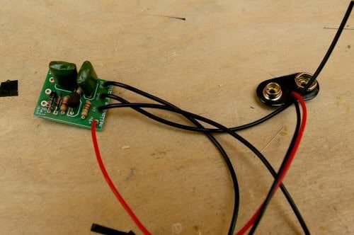
5. WIRES!
You are provided with a battery clip and a length of wire. Cut the wire into 4 equal pieces (should end up abotu 6 inches each). You will set one wire aside but we need three now. There are four holes in the bottom of the pcb, plainly labelled for your convenience: 9v+, In, Out, Ground. The 9v positive connection is provided by the battery clip, so solder the red lead of the battery clip in this hole. Strip the ends of three of your wires and solder these in the other holes and then we can make the appropriate connections later.
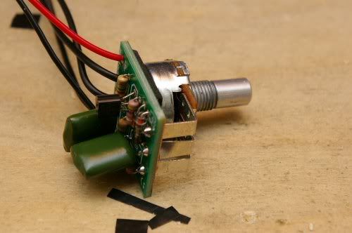
6. POT!
We are using a PCB mount pot which is super convenient. However, because the the pot is metal and will be touching the bottom of the PCB, it could short things out! So all we need to do is put a piece of tape, a sticker, glue a piece of cardboard, anything thin and non-conductive, to completely cover the back of the pot casing. Then we won't short anything. After that, just stick the pot through the three large holes as shown, and solder it in and make sure to use plenty of solder here so that the joints are sturdy. If the legs of your pot come bent up a little just straighten em out so it fits.
7. JACKSSSSSSSSSSSSS
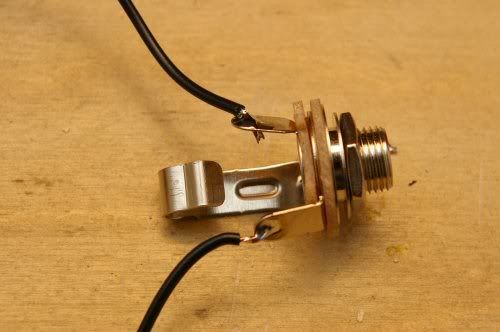
First jack we will solder will be the output (mono, 2 tab) jack:
This jack has two tabs. If you orient the jack as pictured, the upper tab is the sleeve/ground, and the lower tab is called the tip. Solder the Out wire from the PCB to the lower tip tab. (of course make sure you strip the end first!) Use plenty of solder. Next, we take that spare fourth wire we set aside, and we solder that to the upper ground tab. I'll explain why in a minute.
Next is the input (stereo, 3 tabs) jack:
This one is slightly more complicated. If you have the jack oriented as pictured, then this jack also has a tip (rightmost tab) and a sleeve (center tab), but it also has another part called the Ring (leftmost tab). These jacks are used for stereo signals, or in the case of fx pedals they are commonly used for another purpose. It's difficult for me to explain, but here goes: a stereo plug (cable) is divided into three sections that each individually touch the sleeve, ring, and tip, but a mono plug only has two sections which are made to touch sleeve and tip. When you put a mono plug into a stereo jack, the sleeve part of the plug touches the sleeve of the jack AND the ring of the jack. So in a pedal, if nothing is plugged into the input jack, then the ring and the sleeve arent connected, but if you put your guitar cable in the ring and sleeve are now physically connected. This is useful because: If we connect the ground of the battery to the ring it doesnt complete the whole electrical circuit until the ring is connected to the sleeve. So the battery is only ON if you plug your cable into the input jack. Unplug and its OFF and not killing your battery. So there.
LETS SOLDER.
Solder the black lead of the battery clip to the RING (left tab in picture). Solder the OUT wire to the TIP (right tab). Finally, heres where its tricky.... put both the Ground wire from the PCB and the spare wire we soldered to the output (mono) jack to the sleeve of the input jack. Both of them solder to that middle tab. Reason? When you build a pedal the sleeves (ground) are both connected to the metal chassis and so both are grounded togehter like they need to be. But since this is a diy thing and you might end up putting this in a less than conductive enclosure that might not happen, so that spare wire is just insurance that all our grounds are properly connected. In your signal chain all your tips are the hot signal and are broken up by various effects and such, but ALLL the grounds, from your guitar to pedals to amp, etc. are connected one way or the other.
Anyhow, it should look like this:
Ok, it should be all put together. You can hook up a 9volt battery, plug her in (make sure to plug your guitar into the right jack and your amp into the correct jack of course) and test it out. Either it works, or something went wrong and you need help. I promise to help you.
But supposing it works, then you can stick it in something. An altoids can would be a popular choice, I built this one into a salso jar. DIY! Spicy.,
You can also buy parts from pedalpartsplus.com to build it with a footswitch and real enclosure. You can find info on how to wire that up at generalguitargadgets.com or beavisaudio.com or we can all help you here too!
ASK ME AS MANY QUESTIONS AS YOU NEED BEFORE YOU START, and ask as many as you need if it doesn't work! I promise I will help you make it happen!
-
Mel x

- committed

- Posts: 109
- Joined: Thu Mar 26, 2009 2:20 pm
Re: FuzzKit Pre-Orders and Instructions Thread!
Just sent 11 bucks Eric so you can chuck it in with my clean/dirty. 
-
veteransdaypoppy

- IAMILF

- Posts: 2649
- Joined: Wed Mar 25, 2009 1:17 am
Re: FuzzKit Pre-Orders and Instructions Thread!
Sent $22 for two fuzzkits, and you can chuck em in my cc/dc box as well. ")
me so excite.
me so excite.
-
hazelwould

- IAMILFFAMOUS

- Posts: 3590
- Joined: Tue Oct 28, 2008 7:35 pm
Re: FuzzKit Pre-Orders and Instructions Thread!
Sending money tonight :thu:!
Will you include wiring instructions for a 3pdt switch?
Will you include wiring instructions for a 3pdt switch?
-
Mel x
- committed
- Posts: 109
- Joined: Thu Mar 26, 2009 2:20 pm
Re: FuzzKit Pre-Orders and Instructions Thread!
hazelwould wrote:Sending money tonight :thu:!
Will you include wiring instructions for a 3pdt switch?
"Due to lack of time I will not be writing instructions on how to wire it up for bypass, powerjack, or led, but there is plenty of info for the enterprising DIY'er at generalguitargadgets.com, beavisaudio.com, or other sources. This thread will remain open so that anyone may ask questions for help or mods to their kit. I am here to help!"
don't worry dude, we'll get through it together...I'm a total novice too.
-
Caesar

- Supporter

- Posts: 2360
- Joined: Fri Jul 11, 2008 10:15 pm
- Location: Maryland
Re: FuzzKit Pre-Orders and Instructions Thread!
This is the best explanation I've seen on the web for how to wire a 3pdt to a circuit board and add an led.
A long time ago, in a galaxy far far away, God said, "Let there be Lips!" And there were, and they were good, and the lips said...
http://soundcloud.com/gaiusrex
http://soundcloud.com/gaiusrex
-
letsgocoyote
- FAMOUS
- Posts: 1305
- Joined: Mon Oct 01, 2007 4:07 pm
Re: FuzzKit Pre-Orders and Instructions Thread!
excellent link. i will incllude it, as well as other resourcess about bypass wiring in the instructions, tonight
-
hazelwould
- IAMILFFAMOUS
- Posts: 3590
- Joined: Tue Oct 28, 2008 7:35 pm
Re: FuzzKit Pre-Orders and Instructions Thread!
Caesar wrote:This is the best explanation I've seen on the web for how to wire a 3pdt to a circuit board and add an led.
Thanks man!
-
rbtr

- committed
- Posts: 234
- Joined: Sat Mar 28, 2009 5:42 pm
Re: FuzzKit Pre-Orders and Instructions Thread!
very excited!
Will be my first DIY!
Will be my first DIY!
-
ifeellikeatourist

- experienced

- Posts: 817
- Joined: Tue Nov 11, 2008 3:06 am
Re: FuzzKit Pre-Orders and Instructions Thread!
wow..even after the cost of buying an enclosure and 3pdt switch, this kit will still be half the price of the cheapest ggg kit. eric rocks. I am paypalling my order right now.
goroth wrote:Most builders are content on reproducing the same crap. Which is fine. Most guitarists want the same crap.
-
letsgocoyote
- FAMOUS
- Posts: 1305
- Joined: Mon Oct 01, 2007 4:07 pm
Re: FuzzKit Pre-Orders and Instructions Thread!
i just downloaded all the photos today but I need to process/resize them, and then compile the article.
-
steevdeadman

- FAMOUS
- Posts: 1304
- Joined: Sun Jun 14, 2009 11:09 am
- Location: Bronx, NY
- Contact:
Re: FuzzKit Pre-Orders and Instructions Thread!
Are these still available??
"abandon all hope ye who crush that button..." 
Jrmy: Exactly - "the fuzz is strong with that one."
Jrmy: Exactly - "the fuzz is strong with that one."
-
Wizard

- FAMOUS
- Posts: 1579
- Joined: Tue Jun 02, 2009 1:50 am
- Location: Philadelphia, PA
- Contact:
Re: FuzzKit Pre-Orders and Instructions Thread!
steevdeadman wrote:Are these still available??
+1
i can't fucking believe i could have potentially missed this.
I've got a fuzzbox and i'm not afraid to use it
jrmy wrote:And unlike the rest of the country, we recognize Sarcasm as a crucial building block of spoken language. Kind of like umami in cooking.
-
letsgocoyote
- FAMOUS
- Posts: 1305
- Joined: Mon Oct 01, 2007 4:07 pm
Re: FuzzKit Pre-Orders and Instructions Thread!
I may have a couple kits left, let me check and Ill get back to you