Question about power starve / voltage sag circuit

Do-it-yourself pedal building

Moderator: Ghost Hip

Forum rules
The DIY forum is for personal projects (things that are not for sale, not in production), info sharing, peer to peer assistance. No backdoor spamming (DIY posts that are actually advertisements for your business). No clones of in-production pedals. If you have concerns or questions, feel free to PM admin. Thanks so much!
User avatar
Zork
committed
committed
Posts: 229
Joined: Sun Sep 07, 2014 8:45 am

Question about power starve / voltage sag circuit

Post by Zork »

I'm thinking of building a voltage sag circuit for my fuzz pedals.

I have a few questions about the circuit. I plan to build the variant described here:
https://potardesign.com/power-sag-for-guitar-efx/

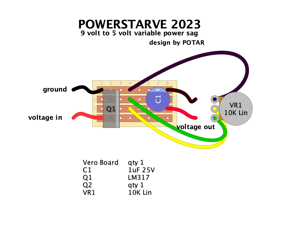
This is the layout provided by Potar Design:

Image

It uses the LM317 voltage regulator. The datasheet (https://www.alldatasheet.com/datasheet- ... LM317.html) suggests as its standard application this circuit here:

Image

...which is basically the same but has a capacitor Cin before the regulator and a resistor R1 between pins 1 and 2.

As far as I understand the Cin capacitor is not necessary but could be depending on the power supply and certainly wouldn't harm, right?

What exactly does R1 do? I understand that it sets a minimum value for the output voltage Vout, so if I fed 9V into the circuit and use the suggested 240ohm resistor, the maximum voltage Vout with the pot fully clockwise would be 9V, the minimum voltage Vout with the pot fully counter clockwise would be about 4V - which would be ideal for the application with fuzz boxes. Is that correct? And if I'm wrong - what value of a resistor would I need and how should it be connected to have the power sag reduce the voltage to about 4V minimum but not less? I feel it makes sense to set minimum output voltage to 4V to utilize the full range of the poti in this application as the fuzz wouldn't do anything useful below half of its range.
User avatar
goroth
HERO
HERO
Posts: 13504
Joined: Wed Jan 25, 2012 3:50 am
Location: Eurothrash: Frozen northern outpost.
Contact:

Re: Question about power starve / voltage sag circuit

Post by goroth »

I shoved this into chatgpt and this is what it reckons:

R1 and R2 form a voltage divider that sets the reference voltage for the LM chip.
The greater R1 is the greater the lowest maximum voltage is.
If R1 is at 240 and R2 is at or near 0 then the minimum output voltage will be around 1.25V.
GPT reckons you need to raise R1 to 528 ohms, so the nearest common resistor would be 560. Even a 470 would get you close enough.
Gone Fission wrote: Thu Oct 24, 2024 2:21 pm That’s quarter-assed at best.
Music out on all streaming services and bandcamp and what not.
Spotify /// Apple Music
My band /// Instagram ///Bandcamp ///
User avatar
Zork
committed
committed
Posts: 229
Joined: Sun Sep 07, 2014 8:45 am

Re: Question about power starve / voltage sag circuit

Post by Zork »

Brilliant method! :idea: Hats off to you!

I didn't know chatgtp could do this. Maybe I should investigate it's possibilities a bit more.

Thank you!
User avatar
goroth
HERO
HERO
Posts: 13504
Joined: Wed Jan 25, 2012 3:50 am
Location: Eurothrash: Frozen northern outpost.
Contact:

Re: Question about power starve / voltage sag circuit

Post by goroth »

Me neither! I just tested it and I know enough about circuits to feel that it wasn't hallucinating, but I couldn't have worked it out myself.
Gone Fission wrote: Thu Oct 24, 2024 2:21 pm That’s quarter-assed at best.
Music out on all streaming services and bandcamp and what not.
Spotify /// Apple Music
My band /// Instagram ///Bandcamp ///
User avatar
Zork
committed
committed
Posts: 229
Joined: Sun Sep 07, 2014 8:45 am

Re: Question about power starve / voltage sag circuit

Post by Zork »

I did a bit mor research on the LM317 and found this extremely useful recource here:

https://www.diyguitarpedals.com.au/shop ... ctator.pdf

Apparently, the LM317 has a voltage drop of about 3V. So, if I wanted to put out a maximum value of 9V Vout, I would need to power the circuit with 12V Vin. The fixed resistor R1 determines the maximum output voltage, so if I would put in a higher voltage, I wouldn't fry my pedal on the output. From the El Dictator file:
This is probably going to be the most commonly used circuit for guitar pedals, as most pedals are rated for 9V max.
With a 12V input DC power supply, the 3V voltage drop on the LM317 should by default bring the maximum output
down to 9V, but due to load requirements, it may not drop the full 3 volts, not to mention the wall supply might push a
few more millivolts than the 12V is has listed on the supply when under a small load. Obviously, input supplies greater
than 12V will be a larger problem. To resolve this possibility, we can use the value of R1 and VR1 to stop the LM317 from
outputting more than 9V.
So, if I chose a value of 10K for the VR or R2, the value of R1 should be R1 = 10000 / ((9 / 1.25) – 1) = 1613 Ohms to prevent the LM317 from putting out a Vout higher than 9V even if Vin would be >12V which in reality would be a 1.6K resistor.

So far, so good. Still, I don't know how to set the minimum voltage output to about 4V. It's of course not necessary, but it would be very nice. I believe the answer is somewhere in this article but I can't quite figure it out yet: https://theelectronicshobbyblog.com/201 ... resistors/
User avatar
Zork
committed
committed
Posts: 229
Joined: Sun Sep 07, 2014 8:45 am

Re: Question about power starve / voltage sag circuit

Post by Zork »

ChatGPT says I need a 3.6K resistor between the potentiometer and ground to set the minimum voltage output to 4V. ;-)
User avatar
crochambeau
IAMILF
IAMILF
Posts: 2203
Joined: Mon Jul 20, 2015 12:49 pm
Location: Cascadia
Contact:

Re: Question about power starve / voltage sag circuit

Post by crochambeau »

In the event Chat GPT is full of shit, you can just slap a rheostat wired pot in there (tie the wiper to one of the legs to make a variable resistor), dial up the preferred conditions, measure it, and substitute a fixed resistor of nearest value.
User avatar
Zork
committed
committed
Posts: 229
Joined: Sun Sep 07, 2014 8:45 am

Re: Question about power starve / voltage sag circuit

Post by Zork »

It should work. I've made a layout with DIY Layout Creator (https://diy-fever.com/software/diylc/) and it should fit in a 1590A enclosure. The print potentiometer is mounted from the backside, the LM317 needs to be folded over so that it lays flat on the vero board, otherwise it wouldn't fit in the enclosure. Note the jumper to the left of R2.

Bildschirmfoto 2024-12-08 um 14.41.46.png
C1 and C2 are not necessary if you use a good power supply, but they don't take up too much space so I figured why not.
idsnowdog
uncommitted
uncommitted
Posts: 5
Joined: Wed Dec 11, 2024 9:57 pm

Re: Question about power starve / voltage sag circuit

Post by idsnowdog »

Will a LM334 work instead of a LM317?
User avatar
Zork
committed
committed
Posts: 229
Joined: Sun Sep 07, 2014 8:45 am

Re: Question about power starve / voltage sag circuit

Post by Zork »

Computer says no:
chatgpt wrote:
The LM334 is a current regulator, not a voltage regulator like the LM317, so it cannot directly replace the LM317 in circuits requiring adjustable voltage output.

Key Differences:
LM317: Adjustable voltage regulator, designed to provide a stable output voltage (up to 1.5A).
LM334: Adjustable current regulator, designed to provide a constant current (typical range: 10mA–100mA).
If you need an adjustable voltage, stick with the LM317 or consider alternatives like:

LM7809/LM7805 for fixed voltages.
LM1117 (LDO) for low dropout regulation.
LM2596 or XL4015 for efficient switching regulation.
idsnowdog
uncommitted
uncommitted
Posts: 5
Joined: Wed Dec 11, 2024 9:57 pm

Re: Question about power starve / voltage sag circuit

Post by idsnowdog »

I bought two lm317s today.
User avatar
Zork
committed
committed
Posts: 229
Joined: Sun Sep 07, 2014 8:45 am

Re: Question about power starve / voltage sag circuit

Post by Zork »

Cool. Let me know how it goes. I plan to build it on breadboard first and measure the actual output. I also want to test if I can leave out any of the capacitors so I have more room in the enclosure. Didn't find the time yet.
idsnowdog
uncommitted
uncommitted
Posts: 5
Joined: Wed Dec 11, 2024 9:57 pm

Re: Question about power starve / voltage sag circuit

Post by idsnowdog »

I built the first one today. It works as advertised but the max voltage is around 7.6V instead of 9V.
User avatar
Zork
committed
committed
Posts: 229
Joined: Sun Sep 07, 2014 8:45 am

Re: Question about power starve / voltage sag circuit

Post by Zork »

Did you use 12V at the input?
idsnowdog
uncommitted
uncommitted
Posts: 5
Joined: Wed Dec 11, 2024 9:57 pm

Re: Question about power starve / voltage sag circuit

Post by idsnowdog »

No, the power supply I used puts out 9.2V. I have a 12V and 18V adapter that are untested. A set of voltage measurement jacks would be a useful addition so you can plug in your multimeter test leads to set the operating voltage. Either that or a voltage indicator.
Post Reply