adding a feedback control to a Shin Ei Fuzz Companion


Moderator: Ghost Hip

Forum rules
The DIY forum is for personal projects (things that are not for sale, not in production), info sharing, peer to peer assistance. No backdoor spamming (DIY posts that are actually advertisements for your business). No clones of in-production pedals. If you have concerns or questions, feel free to PM admin. Thanks so much!

Re: adding a feedback control to a Shin Ei Fuzz Companion

Postby crochambeau » Sat Apr 30, 2016 11:15 pm

moid wrote:I decided to record some samples and plugged it into other pedals, whereupon the feedback knob no longer does anything, except at maximum when it cuts all noise out and passes clean guitar instead... I checked this wasn't a power issues by using different plugs / power sources for the other pedals, so I don't think it's a ground issue (or maybe it is?)... once more any thoughts on how I can get this to now play nicely with its new pedal friends? Thankyou and please don't feel obliged to reply - the pedal is still awesome on its own, but part of me wants to run weird sounds into it to see how it messes them up :)


So, if I am reading this correctly: the pedal, when operated by itself, still works. True?

Few questions:

When you are playing the pedal by itself, and it is working, what exactly is your signal path? I know, I know = guitar or bass into pedal into amp - name names, or better yet, break out the multimeter and measure stuff like DC resistance on the amp input, DC resistance on the instrument output. Keep notes - I don't need to know this shit..

Now, when you add pedals, presumably starting with one: what changes? Again, you want to draw a road map of input/output characters and observe the changes in relation to the measurements.

It might behoove you to build a unity gain buffer or two to "isolate" the effect to a degree. But ultimately, this is a matter of test & observation.

Here are my thoughts: it is possible the feedback path, while it operates in a satisfactory manner locally (in the three piece straight line set-up), may react in a completely different manner when exposed to other active stages, be it the output of an effect or a different type of input load (I have observed, at times, startling performance changes when I take an experimental circuit off my bench (the bench amp has a MOSFET input and is really high impedance) and plugged into an old tube amp that reflects a 100K load.

So, think about where the feedback path is, and consider this might be a situation made for an onboard buffer (TL072 style). I say might, it's hard to say. I have some stuff that will essentially do a filter sweep as I roll down my guitar volume due to the tuned circuit of inductor (pup) + cap (input DC blocker) + resistor (volume control) that a buffer would kill. This is why I mention an external buffer you can move around and play with before committing to the change.

Also, EYG poses a really good point in that it would be a good idea to replicate the circuit, taking care with assembly. That way you have a spare, or something to sling and a whole 'nother round of the best education.
I've got to get off my ass and bring to reality that what has been quoted through existence.

Rochambeau Musical Apparatus
Reverb storefront
Shark Tank
crochambeau

User avatar
IAMILF
IAMILF
 
Posts: 2162
Joined: Mon Jul 20, 2015 12:49 pm
Location: Cascadia

Re: adding a feedback control to a Shin Ei Fuzz Companion

Postby moid » Sun May 01, 2016 8:14 pm

eatyourguitar wrote:building it on vero, and dropping it, and I don't know how much experience you have, I would say maybe it would be good to build another one but this time clean the copper with scotchbrite before you do anything and then finish soldering in less than 24 hours to avoid oxide build up. I would even clean with alcohol again before soldering. watch the these videos. only difference is that you use scotchbrite instead of the rubber eraser in the video.

http://www.amazon.com/Scotch-Brite-Heav ... 003FYJ83S/


Wow thanks eatyourguitar - that video on soldering was really interesting - I didn't know you were supposed to clean surfaces before soldering them. Scotchbrite is not something I've encountered before; I looked at their website and they seem to have at least 20 products that clean surfaces in the way you are mentioning - do you mean with a liquid cleaner (possibly alcohol based) or a scouring product like a pad? Any hints would be great before I buy the wrong thing and destroy whatever board I'm working on. I'm based in the UK and I'm not sure how much of this stuff is available over here, but I'm sure Amazon or Ebay will have it somewhere! Regarding the time spent - the board was populated in about an hour, but then because work has been horrible this year, the board sat in a box for four months before I got a chance to attach cables and knobs, jacks, power etc.

The second video about DIP chips - I use DIP sockets for these, I didn't realise that I need to check the solder falls through the hole from the solder side of the board to the upper (component) side... I'm going to have to check a non functioning tremolo build now, perhaps that's what is keeping it from flashing an LED. It looks like I also need a thinner soldering iron tip... I think I'll watch the rest of that series!

My previous experience is limited to say the least - I don't have a background in electrical engineering (or anything practical or musical for that matter), and I find this stuff quite complex but fascinating, so I hope eventually things will sink in more. Most of my builds work first time (when I follow the layout and don't change anything - the exception being tremolos which seem to hate me) but the creative part of me wants to fiddle with things and alter them to create new sounds, and that's where a lack of technical knowledge/electrical theory causes issues...


crochambeau wrote:
So, if I am reading this correctly: the pedal, when operated by itself, still works. True?


True - it's a crazy thing :)

crochambeau wrote:Few questions:

When you are playing the pedal by itself, and it is working, what exactly is your signal path? I know, I know = guitar or bass into pedal into amp - name names, or better yet, break out the multimeter and measure stuff like DC resistance on the amp input, DC resistance on the instrument output. Keep notes - I don't need to know this shit..


Guitar was a Yamaha RGX110 into the pedal via a 10foot / 3m cable, then a 2 foot / 60cm cable to the amplifier which is an Ampeg BA-108 (bass amplifier, solid state). The Bass guitar was a Harley Benton Short Scale passive bass. I've also tried a Cort G100 guitar in the same combination of pedal/cable/ amplifier.

How do you measure DC resistance on the amp input? When the cable is plugged in there's no way I can get the probe from my DMM into the socket?

crochambeau wrote:Now, when you add pedals, presumably starting with one: what changes? Again, you want to draw a road map of input/output characters and observe the changes in relation to the measurements.

It might behoove you to build a unity gain buffer or two to "isolate" the effect to a degree. But ultimately, this is a matter of test & observation.

Here are my thoughts: it is possible the feedback path, while it operates in a satisfactory manner locally (in the three piece straight line set-up), may react in a completely different manner when exposed to other active stages, be it the output of an effect or a different type of input load (I have observed, at times, startling performance changes when I take an experimental circuit off my bench (the bench amp has a MOSFET input and is really high impedance) and plugged into an old tube amp that reflects a 100K load.


I think the above questions are best answered below your next quote thanks:


crochambeau wrote:So, think about where the feedback path is, and consider this might be a situation made for an onboard buffer (TL072 style). I say might, it's hard to say. I have some stuff that will essentially do a filter sweep as I roll down my guitar volume due to the tuned circuit of inductor (pup) + cap (input DC blocker) + resistor (volume control) that a buffer would kill. This is why I mention an external buffer you can move around and play with before committing to the change.

Also, EYG poses a really good point in that it would be a good idea to replicate the circuit, taking care with assembly. That way you have a spare, or something to sling and a whole 'nother round of the best education.


OK you said buffer and I thought I wondered if I have any pedals with buffers in them; step forward the Boss BF2 Flanger in its purple glory and I plugged the guitar into the Boss pedal, then a cable from that to the Fuzz, and from the fuzz to the amplifier. I made them both use the same power supply and voilà, success! The feedback control now oscillates and causes damage (albeit less than before, but that's OK) and the pedal works and can even be plugged into other pedals with success :) And flanger into fuzz is always a good sound in my opinion. It seems I need to build a buffer - I looked for TL072 buffers and found this:

Image

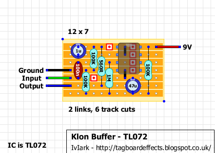
Does that look like a possible circuit to try? I've got all the parts for this already, but I might not get a chance to make it until next weekend. I think I'll want it on a footswitch so I can turn it off for extreme chaos if the pedal isn't plugged into anything else :)

Thanks to both of you for your patience :)
moid

User avatar
experienced
experienced
 
Posts: 694
Joined: Sun May 03, 2015 6:35 pm

Re: adding a feedback control to a Shin Ei Fuzz Companion

Postby eatyourguitar » Sun May 01, 2016 8:54 pm

If you dont have scotchbrite you can use any 600 grit sand paper but you only need a quick pass to wipe the oxide off. If you keep sanding you will have no copper left or you might scrape the tin coating off the copper if you are building from a kit that is tinned. I would use the sandpaper everywhere they used the rubber eraser in the video. I would also use alchohal on the board imediately before soldering. You should be good for a day or a week. A day is best practice. People get by on much less respect but the reliability and longevity is what it is. There are much more stringent soldering specifications for medical, military, space, scientific equipment but we are not doing that with guitar pedals or at least I hope not. I use the scotchbrite pads without the yellow sponge. They saved my ass restoring a vintage drum machine that was in the navy at sea.
WWW.EATYOURGUITAR.COM <---- MY DIY STUFF
eatyourguitar

User avatar
IAMILFFAMOUS
IAMILFFAMOUS
 
Posts: 3127
Joined: Sun Oct 03, 2010 12:37 pm
Location: USA, RI

Re: adding a feedback control to a Shin Ei Fuzz Companion

Postby crochambeau » Sun May 01, 2016 11:36 pm

moid wrote:How do you measure DC resistance on the amp input? When the cable is plugged in there's no way I can get the probe from my DMM into the socket?


Some cables will allow you to unscrew the can and measure directly from the solder points on the plug, do that if you can. I just grab a dual gang banana to 1/4" and plug directly into my meter - but that is a side effect of my using some oddball shit in sound.

That looks like a fine buffer.

Regarding sand paper, do not, under any circumstances, grab a coarser grit than 600 and tell yourself you'll just sand it lightly. A lot of trace material on a PCB will not tolerate that (I'm speaking from experience on this one). You just want to cut through the oxidized layer, you don't need to eat off of it. I've even just scuffed a pad with the end of a pick/screwdriver when I'm in a hurry.
I've got to get off my ass and bring to reality that what has been quoted through existence.

Rochambeau Musical Apparatus
Reverb storefront
Shark Tank
crochambeau

User avatar
IAMILF
IAMILF
 
Posts: 2162
Joined: Mon Jul 20, 2015 12:49 pm
Location: Cascadia

Re: adding a feedback control to a Shin Ei Fuzz Companion

Postby moid » Mon May 02, 2016 7:25 pm

eatyourguitar wrote:If you dont have scotchbrite you can use any 600 grit sand paper but you only need a quick pass to wipe the oxide off. If you keep sanding you will have no copper left or you might scrape the tin coating off the copper if you are building from a kit that is tinned. I would use the sandpaper everywhere they used the rubber eraser in the video. I would also use alchohal on the board imediately before soldering. You should be good for a day or a week. A day is best practice. People get by on much less respect but the reliability and longevity is what it is. There are much more stringent soldering specifications for medical, military, space, scientific equipment but we are not doing that with guitar pedals or at least I hope not. I use the scotchbrite pads without the yellow sponge. They saved my ass restoring a vintage drum machine that was in the navy at sea.


Thanks eatyourguitar that will help me search for the right thing (and not wreck a veroboard!).

crochambeau wrote:
moid wrote:How do you measure DC resistance on the amp input? When the cable is plugged in there's no way I can get the probe from my DMM into the socket?


Some cables will allow you to unscrew the can and measure directly from the solder points on the plug, do that if you can. I just grab a dual gang banana to 1/4" and plug directly into my meter - but that is a side effect of my using some oddball shit in sound.

That looks like a fine buffer.

Regarding sand paper, do not, under any circumstances, grab a coarser grit than 600 and tell yourself you'll just sand it lightly. A lot of trace material on a PCB will not tolerate that (I'm speaking from experience on this one). You just want to cut through the oxidized layer, you don't need to eat off of it. I've even just scuffed a pad with the end of a pick/screwdriver when I'm in a hurry.


Wow I never thought of unscrewing the cable... ahhh just checked my smaller cables are all moulded plastic jobs, but some of my longer cables can be unscrewed. Hmmm the dual gang banana - am I right in thinking I would attach the ground probe to one of these and the positive to the other? So I wouldn't be connected to the amp at all? I do own some dual banana cables that start as stereo 1/8 inch but I have a plug that turns them into 1/4 inch.

I had a (probably) crazy thought about the buffer. I will need to put it in a separate enclosure (the current one is absolutely stuffed) so how silly an idea is it to have the signal coming into this new buffer pedal split in two from the input jack - one side goes to the buffer circuit, the other side goes to lug 1 of a 100K lin pot. The circuit output connects to lug3 of that pot and lug two goes to the output of the pedal. The reason for this is it would (in my head of course) allow me to blend between high impedance from the guitar and low impedance from the buffer circuit, so I could dial in exactly how crazy I want the oscillations to go on the fuzz pedal by raising / lowering the impedance. Knowing my luck this is the electrical equivalent of crossing the streams in Ghostbusters... if this potentially does work, should I add a boost to the clean side to make up for any increase in sound from the buffer circuit - I saw it had an opamp, so I assume that will make any sound going through it louder? Thanks again.
moid

User avatar
experienced
experienced
 
Posts: 694
Joined: Sun May 03, 2015 6:35 pm

Re: adding a feedback control to a Shin Ei Fuzz Companion

Postby crochambeau » Mon May 02, 2016 8:26 pm

Sometimes electrons find a more direct path our somewhat blind minds miss, best to just experiment with it and see.

I'll take a picture of what I meant by the dual banana to 1/4" cable I use to peek at the static (and therefore somewhat inconclusive, yet still useful) state of the circuit facing the jack.
I've got to get off my ass and bring to reality that what has been quoted through existence.

Rochambeau Musical Apparatus
Reverb storefront
Shark Tank
crochambeau

User avatar
IAMILF
IAMILF
 
Posts: 2162
Joined: Mon Jul 20, 2015 12:49 pm
Location: Cascadia

Re: adding a feedback control to a Shin Ei Fuzz Companion

Postby moid » Tue May 03, 2016 8:00 pm

Thanks very much, that'll be useful - and in the sake of science and loud oscillating noises, I'll try making the buffer the way I visualise it and we'll see what happens (this might be a little while though, work is going to be horrible until early June)
moid

User avatar
experienced
experienced
 
Posts: 694
Joined: Sun May 03, 2015 6:35 pm

Re: adding a feedback control to a Shin Ei Fuzz Companion

Postby wjmwpg » Sat Mar 13, 2021 1:03 am

Ben79 wrote:There's a mod by Mark Hammer to alter the 'body' of the tone.

Another thing I've done successfully is incorporate a "body" control. You see the 100k47k pair in series, between V+ and the collector of Q2? There is a .047uf cap in parallel with the 100k resistor. By varying how much of the entire 147k resistance that cap straddles, you can vary the bottom/body of the resulting sound.

One possible way to do this would be to connect an 1k resistor between V+ and one outside lug of a 100k pot, and a 33k resistor between the other outside lug and the collector of Q2. You now have 151k of resistance between V+ and the collector. Given that pots are usually a little lower than their nominal value, that probably puits you spot on 147k. Now, connect the .047uf cap between the wiper of that pot and V+. The total V+-to-collector resistance will remain fixed, but the resistance in parallel with the cap will be varied from 18k to 118k; from thinner-sounding than stock, to something almost suitable for a bass. Try it and see if you like it.

Hi, I’m a bit new to all this, but I’m playing with the FY2 circuit and have played a bit with altering this 100K/.047μ pair to mixed results. I’m eager to try this method as described, but don’t understand the math on the resistances. A 1K resistor and the span of a 100K pot, and a 33K resistor would only come to 134Kohms, not 151K. What (probably very) obvious thing am I missing?
wjmwpg

uncommitted
uncommitted
 
Posts: 2
Joined: Sat Jan 09, 2021 5:29 pm

Re: adding a feedback control to a Shin Ei Fuzz Companion

Postby wjmwpg » Mon Mar 15, 2021 12:14 am

I get it now. Where it says 1K between V+ and the pot it should say 18K between V+ and the pot (and still the 33K on the other side of the pot . . . equalling 151K if the pot is a true 100K.)
wjmwpg

uncommitted
uncommitted
 
Posts: 2
Joined: Sat Jan 09, 2021 5:29 pm

Previous

Return to DIY Effects


Who is online

Users browsing this forum: No registered users and 7 guests


Sponsored Ad. (Please no inflated/repetitive clicking. Thanks!)


ilovefuzz.com is not responsible for user-submitted content. Users participate at their own discretion and risk.