The Expression Multiplexer - Schematics and Infos
Tue Jun 30, 2020 1:55 pm
Hi all!
This is the latest addition to the MOM-D family - the Expression Multiplexer.
I needed to be able to control multiple expression inputs at the same time, while still being able to not control them all at the same time. Yeah. I know.
Therefore, the ExpMultiplexer was born. It is an Arduino based controller to support the whole open source spirit. I know that parts like the digital potentiometers used here can be hard to get for a hobbyist, but it is not impossible and I could support with getting them if needed.
Shitty pic:

It's a 4-channel expression expander.
One Exp input lets you control up to 4 exp inputs.
Each channel can be turned on/off separately or you can save patches (4 of them) for having a combination of channels enabled at once.
Also 4 different tapers are available for the expression outputs.
Description (I put it in spoiler tags because it is massive):
Schematic is on Google Drive: https://drive.google.com/file/d/1K54_snqwXJ2GVTFHqD-3ycufj98Hu863/view?usp=sharing
Let's break down the different circuit blocks:
First off - Supply:

Consists of 9V input with series diode for polarity protection and buffer cap, 5V regulator for logic supply and a charge pump for the bipolar reference voltage supply of the digital potentiometers.
Digital Potentiometers:
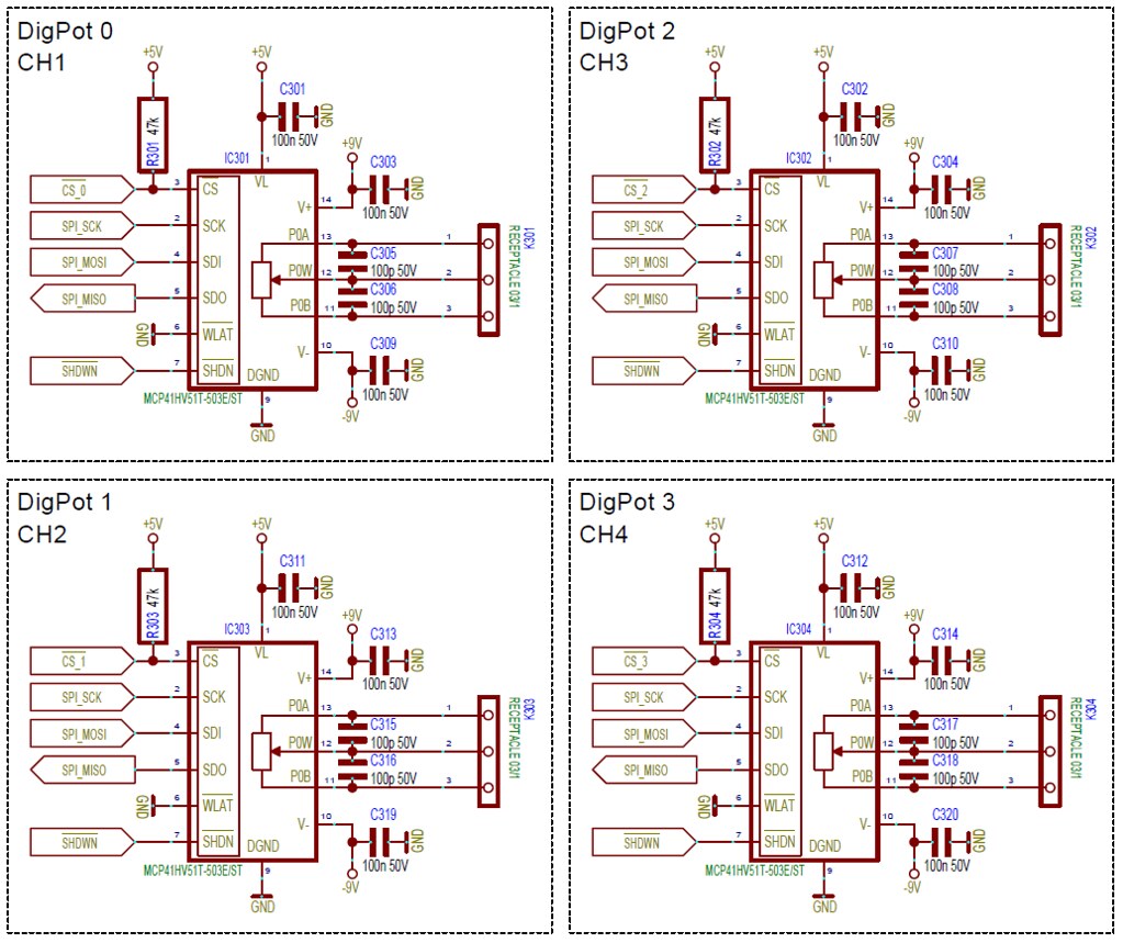
One for each channel.
The 100p caps on the outputs are optional and are normally not assembled.
Controller:
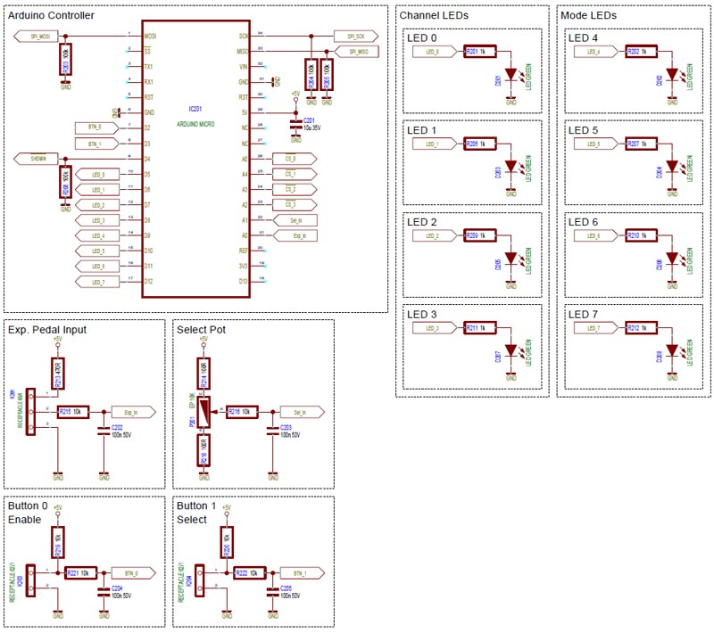
An Arduino Micro is used to control the whole thing.
Digital Pots are controlled via SPI. Buttons and LEDs go to GPIOs, Exp. Input and Select Knob are sampled with the ADC.
Source Code is on GitHub.
Be warned, it was written in a drunk coding frenzy one lonely evening...

GitHub Link: https://github.com/Schlattner/ExpMult_Arduino-FW
If you need anything, just ask!
This is the latest addition to the MOM-D family - the Expression Multiplexer.
I needed to be able to control multiple expression inputs at the same time, while still being able to not control them all at the same time. Yeah. I know.
Therefore, the ExpMultiplexer was born. It is an Arduino based controller to support the whole open source spirit. I know that parts like the digital potentiometers used here can be hard to get for a hobbyist, but it is not impossible and I could support with getting them if needed.
Shitty pic:
It's a 4-channel expression expander.
One Exp input lets you control up to 4 exp inputs.
Each channel can be turned on/off separately or you can save patches (4 of them) for having a combination of channels enabled at once.
Also 4 different tapers are available for the expression outputs.
Description (I put it in spoiler tags because it is massive):
SPOILER : show
Schematic is on Google Drive: https://drive.google.com/file/d/1K54_snqwXJ2GVTFHqD-3ycufj98Hu863/view?usp=sharing
Let's break down the different circuit blocks:
First off - Supply:
Consists of 9V input with series diode for polarity protection and buffer cap, 5V regulator for logic supply and a charge pump for the bipolar reference voltage supply of the digital potentiometers.
Digital Potentiometers:
One for each channel.
The 100p caps on the outputs are optional and are normally not assembled.
Controller:
An Arduino Micro is used to control the whole thing.
Digital Pots are controlled via SPI. Buttons and LEDs go to GPIOs, Exp. Input and Select Knob are sampled with the ADC.
Source Code is on GitHub.
Be warned, it was written in a drunk coding frenzy one lonely evening...
GitHub Link: https://github.com/Schlattner/ExpMult_Arduino-FW
If you need anything, just ask!
Re: The Expression Multiplexer - Schematics and Infos
Sun Jul 12, 2020 4:31 am
PCB Documentation is now online!
Check the Google Drive for:
Schematic drawing: https://drive.google.com/file/d/1K54_snqwXJ2GVTFHqD-3ycufj98Hu863/view?usp=sharing
PCB Gerbers: https://drive.google.com/file/d/1KS-IAJeQdQbzsUCSaeweiMa0y94zdwNY/view?usp=sharing
BOM/Partlist: https://drive.google.com/file/d/1lnQx03bTf_NgQlJsqkyubtluavmLYQwM/view?usp=sharing
Pick and Place Data: https://drive.google.com/file/d/1J92c0t6QQ_Tc34QirqqWBFHVh5v-GtUF/view?usp=sharing
Assembly Drawing: https://drive.google.com/file/d/1Op-lsKbxKdgHa4IEMRu1K6vCybXG8dt4/view?usp=sharing
The SMD Footprints are a compromise for reflow and manual soldering. It should be possible to use the footprints in a pick and place assembly line, but mainly the idea is to make hand soldering easier.
Re: The Expression Multiplexer - Schematics and Infos
Wed Jul 22, 2020 6:17 pm
My boner!
Re: The Expression Multiplexer - Schematics and Infos
Thu Nov 12, 2020 5:13 am
I had fun using this pedal!
I am pretty bone headed these days and I didn't really understand setting saving and whatever. The way I was using it seemed to be channel 1 plus 1 other channel, which I could select.
The range on the digital pots was good and I could get some really cool sounds out of it.
The interface was simple, which is good, but I'm trash with secondary functions, saving stuff and whatever. This is one of the reasons I've gotten rid of the Ct5. I just couldn't remember what was happening with what. So I'm going to say that it was a super nice pedal, suited to a person who is more prepared to spend time understanding stuff")
I am pretty bone headed these days and I didn't really understand setting saving and whatever. The way I was using it seemed to be channel 1 plus 1 other channel, which I could select.
The range on the digital pots was good and I could get some really cool sounds out of it.
The interface was simple, which is good, but I'm trash with secondary functions, saving stuff and whatever. This is one of the reasons I've gotten rid of the Ct5. I just couldn't remember what was happening with what. So I'm going to say that it was a super nice pedal, suited to a person who is more prepared to spend time understanding stuff