Page 95 of 409
Re: Let's see your finished DIY projects!
Posted: Thu Sep 08, 2011 7:51 pm
by Jero
Some of the more random stuff I've done recently...
Repaint of a fuzzface Scruffie built a couple years ago and a voltage divider.
Voltage Divider for mordecainyc
EHX Pulsar (orig ver) with momentary waveform switch. The etch didn't work right, but I still like it.
Re: Let's see your finished DIY projects!
Posted: Thu Sep 08, 2011 8:01 pm
by Scruffie
Jero wrote:Some of the more random stuff I've done recently...
Repaint of a fuzzface Scruffie built a couple years ago and a voltage divider.
S6300099.JPG
Voltage Divider for mordecainyc
EHX Pulsar (orig ver) with momentary waveform switch. The etch didn't work right, but it's hard to see in the picture anyway.
Hol-eee Shit, the $30 Fuzz is still alive!?

Loving its new look!
How did you get on with the Pulsar Tick Fixes?
Re: Let's see your finished DIY projects!
Posted: Thu Sep 08, 2011 8:51 pm
by Fuzz_Pi
Rygot wrote:For another ILF'er.

FY2 with added 2 knob tone stack and scoop trim > Green Ringer


Cool idea
Re: Let's see your finished DIY projects!
Posted: Fri Sep 09, 2011 3:47 am
by Pollinator95
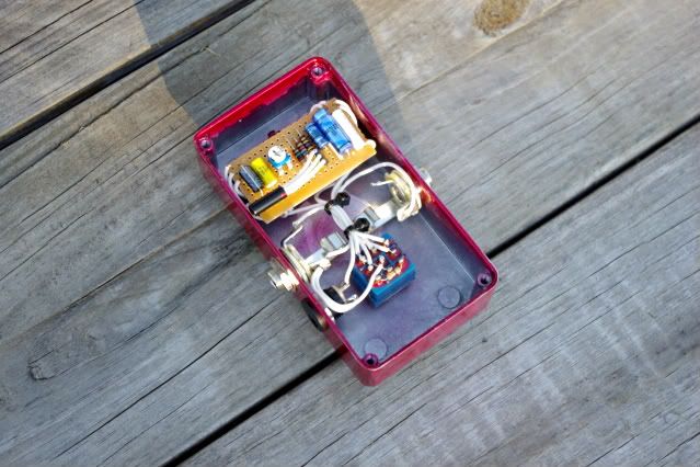
eatyourguitar wrote:glad you got it working. you might want to put the board closer to the pots next time if you have 3 pots and they all go directly to the board. there is a trick too if you have a vol pot at the end of the circuit for example. you could run 3 wires from the board to the pot and the output from the board to the switch. thats 4 wires. or you could just take the lug 3 from the board and wire it to the vol pot. the other lugs of the vol pot go to the switch and lug 1 to ground. thats 3 wires instead of 4 but only 1 wire that connects to the board. MUuuuuch cleaner in most cases.
Thanks for the tips!

I meant to put the PCB over the pots with standoffs, but I bought a MASSIVE tone pot. Add on the extra offboard wiring for the tone control, and the PCB just wouldn´t fit. So I had to wedge it between the footswitch and a bit of sponge wrapped in electrical tape

.
Re: Let's see your finished DIY projects!
Posted: Fri Sep 09, 2011 5:30 pm
by LaoWiz
Rygot wrote:For another ILF'er.
FY2 with added 2 knob tone stack and scoop trim > Green Ringer
Need some clips! What did you do with the tone stack? Very nice. I think there needs to be a DIY demo page with sound bites or vids.
Re: Let's see your finished DIY projects!
Posted: Fri Sep 09, 2011 11:22 pm
by Rygot
Already mailed it out otherwise I would do some clips. Maybe he can do some?

As for the tone stack, I kept the original "fuzz" control in the fy-2. Added the Beavis audio "better tone stack", and then a boost to compensate for all the volume loss. Simple but effective.
The scoop trim pot was a mod by, I believe, mark hammer. Just 50k between a cap and ground. Adds a ton of volume when you take away the scoop.
Oh, a DIY demo page would be pretty cool. I've got plenty of stuff on the way.

Re: Let's see your finished DIY projects!
Posted: Sat Sep 10, 2011 11:00 am
by Schlatte
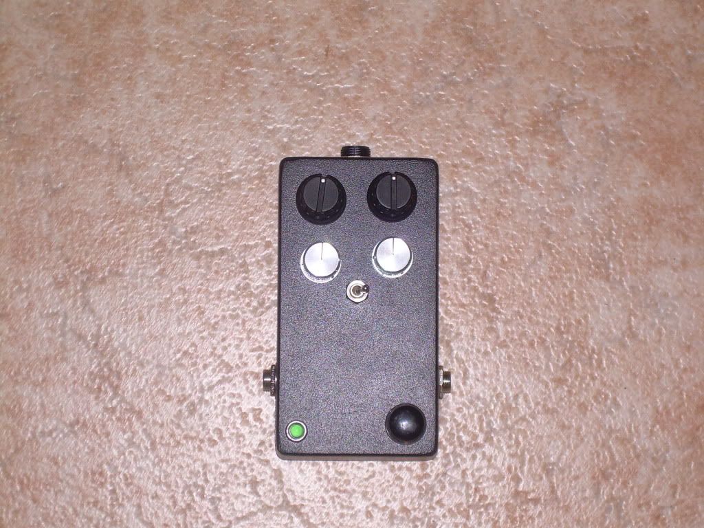
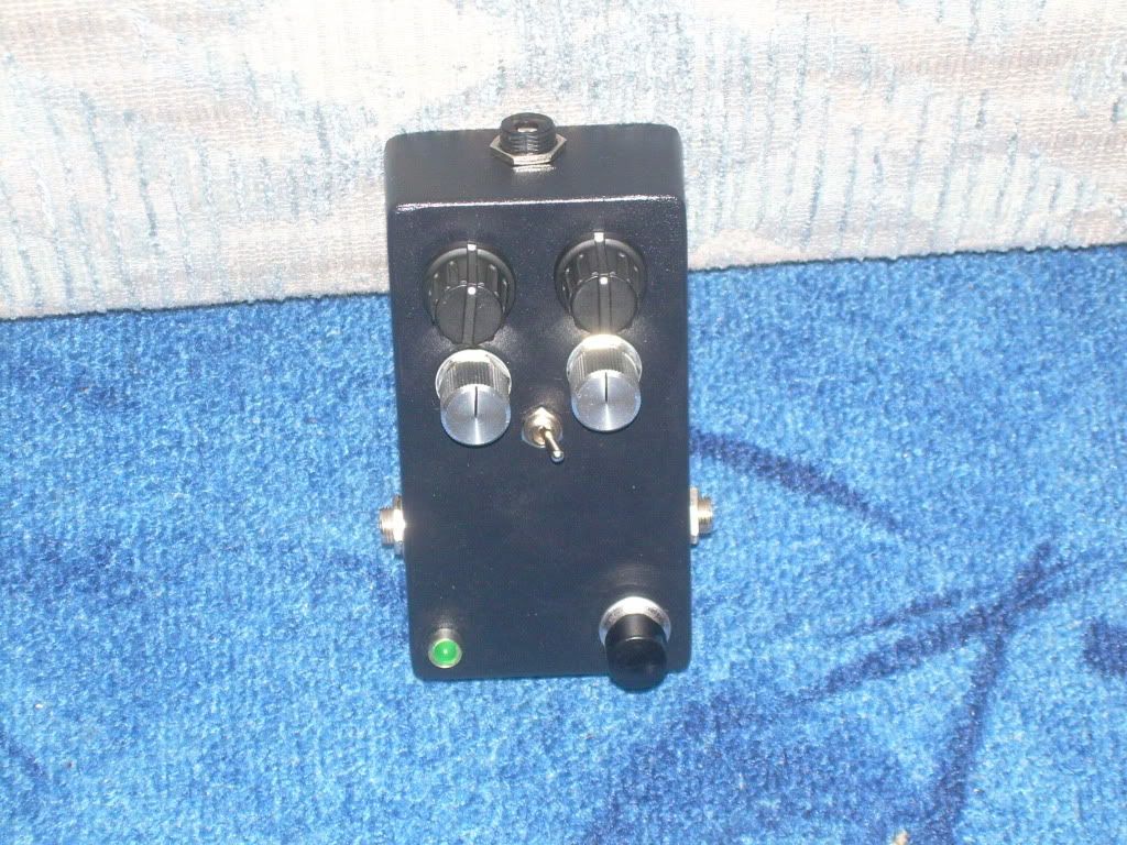
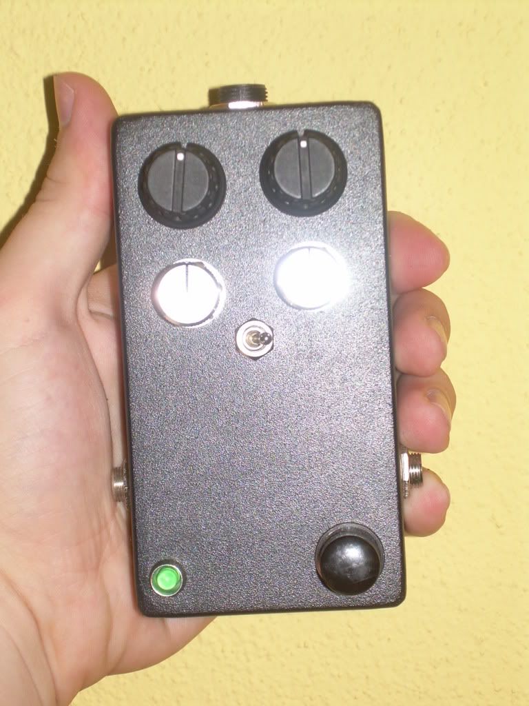
Special custom edition of the "Fuzzler" fuzz pedal, my first build with relay based true bypass.
Controls from left to right:
the two black knobs are Volume and Gain
the two silver knobs are Tone and Feedback Control
the switch is for the feedback.
Sexy pics:
Sounds awesome and does some wacky snazzy stuff with the feedback switch enabled

Re: Let's see your finished DIY projects!
Posted: Sat Sep 10, 2011 12:57 pm
by eatyourguitar


pretty much just a silicon fuzz face with a starved Q2 and a big ass cap on the power rails to simulate battery capacitance. for whatever reason, it gets less fuzzy as you get closer to the proper bias. but with the Q2 collector at 2.5v battery or 3.5v on wall power, it has a really cool fuzz sound. I found it on the breadboard and it was just a matter of adding the cap and biasing at 3.5v instead of 2.5v to get back to the same sound. transistors are 2N5133 Hfe 79 and Q2 2n2222 hfe ?
Re: Let's see your finished DIY projects!
Posted: Sat Sep 10, 2011 5:56 pm
by ARC Effects

Some mojo components/flame finish/black glass CV7112 transistor goodness
Re: Let's see your finished DIY projects!
Posted: Sat Sep 10, 2011 6:01 pm
by warwick.hoy
Nice job on the Companion Fuzz,...looks secksy.
Re: Let's see your finished DIY projects!
Posted: Sat Sep 10, 2011 11:35 pm
by BlindtoFaith
StupidDream88 wrote:Some mojo components/flame finish/black glass CV7112 transistor goodness
WHat it is? HA
Re: Let's see your finished DIY projects!
Posted: Sat Sep 10, 2011 11:45 pm
by John Lyons
Range master with input cap blend?
Re: Let's see your finished DIY projects!
Posted: Sun Sep 11, 2011 11:46 am
by Jwar
Can any of you DIY types tell me how to add a 9v adapter into a pedal. Just got one in trade an it only has the option for a battery, and you have to remove the back plate to put the battery in. So pain in the ass. The pedal sounds amazing though! Is it fairly simple to do? Help me!
Re: Let's see your finished DIY projects!
Posted: Sun Sep 11, 2011 11:54 am
by Schlatte
jwar wrote:Can any of you DIY types tell me how to add a 9v adapter into a pedal. Just got one in trade an it only has the option for a battery, and you have to remove the back plate to put the battery in. So pain in the ass. The pedal sounds amazing though! Is it fairly simple to do? Help me!
just get an isolated dc jack with a switching contact- if you want to use the battery too. if you just want to throw out the battery and never use one again you just need to get an isolated dc jack.
like this for example:
http://www.mammothelectronics.com/4SJK-101DCXT-Round-External-Nut-DC-Power-Jack-p/600-1000-xt.htmstandard 5mm with 2,1mm tip. isolated because your enclosure is probably grounded and if you want to use boss style supplies (neg. tip) a non-isolated dc jack would connect the sleeve of your dc plug to the enclosure and short everything out.
so just drill a hole into the enclosure (make sure you have enough space for everything) so you can fit your jack in, and wire it like this:
cut the red (+) wire from the battery clip and rewire everything:

hope it helped
Re: Let's see your finished DIY projects!
Posted: Sun Sep 11, 2011 6:08 pm
by Jwar
Schlatte wrote:jwar wrote:Can any of you DIY types tell me how to add a 9v adapter into a pedal. Just got one in trade an it only has the option for a battery, and you have to remove the back plate to put the battery in. So pain in the ass. The pedal sounds amazing though! Is it fairly simple to do? Help me!
just get an isolated dc jack with a switching contact- if you want to use the battery too. if you just want to throw out the battery and never use one again you just need to get an isolated dc jack.
like this for example:
http://www.mammothelectronics.com/4SJK-101DCXT-Round-External-Nut-DC-Power-Jack-p/600-1000-xt.htmstandard 5mm with 2,1mm tip. isolated because your enclosure is probably grounded and if you want to use boss style supplies (neg. tip) a non-isolated dc jack would connect the sleeve of your dc plug to the enclosure and short everything out.
so just drill a hole into the enclosure (make sure you have enough space for everything) so you can fit your jack in, and wire it like this:
cut the red (+) wire from the battery clip and rewire everything:
hope it helped
Thank you! Hopefully I'm smart enough to install this!
