Let me see what I can dig up on them. I read an interesting article about their advantages in the PI over regular 12ax7s.
EDIT: This is exactly the article I read.
Got quite a bit of info in there, mentions gain, current output and transconductance in 12ax7s, 5751s and 12at7s. Worth a read, I think.
Tech help for my Russian death box please
31 posts
• Page 2 of 3 • 1, 2, 3
Re: Tech help for my Russian death box please
![]() by HeavyXIII » Fri Aug 09, 2013 3:55 pm
by HeavyXIII » Fri Aug 09, 2013 3:55 pm
Good Deal List: bearbeams, pena_55, sonidero, greyscales, ChetMagongalo, xchristophex, Monkey Boy, krautrocker, osbornkt
Carkoon, my Posty, Doomy, Dadcore band
FACEBOOK | https://www.facebook.com/carkoondoom/
BANDCAMP | https://carkoon.bandcamp.com/releases
D.o.S. wrote:Like, I don't just listen to Whores when I'm sitting alone in my room with the lights off staring at a wall. Sometimes I listen to it with the lights on, too.
Carkoon, my Posty, Doomy, Dadcore band
FACEBOOK | https://www.facebook.com/carkoondoom/
BANDCAMP | https://carkoon.bandcamp.com/releases
-
HeavyXIII

- experienced

- Posts: 902
- Joined: Mon Feb 18, 2013 3:51 pm
Re: Tech help for my Russian death box please
![]() by Iommic Pope » Fri Aug 09, 2013 10:15 pm
by Iommic Pope » Fri Aug 09, 2013 10:15 pm
Hey man, I read that article yesterday and it pretty much made my mind up. Cheers though, its good reading for anyone else considering it.
Some dude on the bay has some relatively cheap tubes going on and some make an offer tubes, so I put in an offer on a JAN and 2 tungsol 12ax7s for the preamp (it needs some new ones anyhow)....see if he bites at $10 a pop.
I can post the link if anyone else is in need of some cheap(ish) tubes. Who knows, you might be able to offer him something low and nab some cheap ones?
WWPD?
fcknoise wrote:You are all fucking tryhard effort posting nerds
Invisible Man wrote:I'm probably the most humble person I know. I feel good about smelling my own butthole.
Jesus Was a Robot wrote:Did you just assume Billy Corgan's dildo preference??
-
Iommic Pope

- IAMILFFAMOUS

- Posts: 11405
- Joined: Tue Mar 05, 2013 8:41 pm
- Location: Frimmin' on the Fram
Re: Tech help for my Russian death box please
![]() by Iommic Pope » Sun Aug 11, 2013 3:46 am
by Iommic Pope » Sun Aug 11, 2013 3:46 am
Ended up getting my tubes at $10.99 a piece. Also just spent way more than I should have getting some caps for a recap. Time to overhaul the old girl.
Went with JJs for the big ones. They had the closest values and the best price, word is they're ok sounding too. Anyone used em?
Went with JJs for the big ones. They had the closest values and the best price, word is they're ok sounding too. Anyone used em?
WWPD?
fcknoise wrote:You are all fucking tryhard effort posting nerds
Invisible Man wrote:I'm probably the most humble person I know. I feel good about smelling my own butthole.
Jesus Was a Robot wrote:Did you just assume Billy Corgan's dildo preference??
-
Iommic Pope
- IAMILFFAMOUS
- Posts: 11405
- Joined: Tue Mar 05, 2013 8:41 pm
- Location: Frimmin' on the Fram
Re: Tech help for my Russian death box please
![]() by HeavyXIII » Sun Aug 11, 2013 11:31 am
by HeavyXIII » Sun Aug 11, 2013 11:31 am
I like my JJs  I had some Tungsols, but they do weird stuff to the mids that didn't like if I didn't have at least 1 JJ in there. My amp had Ruby tubes in power amp when I first got it, and they sound pretty interesting, but my tech recommended JJs there too, and I don't regret the switch.
The 12at7s I've got are JAN Phillips, but I can't for the life of me remember what inspired me to get them. It might've been that they're supposed to be military spec and tough, which is what I wanted out of my PI, but I don't really remember. Good stuff though.
I had some Tungsols, but they do weird stuff to the mids that didn't like if I didn't have at least 1 JJ in there. My amp had Ruby tubes in power amp when I first got it, and they sound pretty interesting, but my tech recommended JJs there too, and I don't regret the switch.The 12at7s I've got are JAN Phillips, but I can't for the life of me remember what inspired me to get them. It might've been that they're supposed to be military spec and tough, which is what I wanted out of my PI, but I don't really remember. Good stuff though.
Last edited by HeavyXIII on Mon Aug 12, 2013 12:36 am, edited 1 time in total.
Good Deal List: bearbeams, pena_55, sonidero, greyscales, ChetMagongalo, xchristophex, Monkey Boy, krautrocker, osbornkt
Carkoon, my Posty, Doomy, Dadcore band
FACEBOOK | https://www.facebook.com/carkoondoom/
BANDCAMP | https://carkoon.bandcamp.com/releases
D.o.S. wrote:Like, I don't just listen to Whores when I'm sitting alone in my room with the lights off staring at a wall. Sometimes I listen to it with the lights on, too.
Carkoon, my Posty, Doomy, Dadcore band
FACEBOOK | https://www.facebook.com/carkoondoom/
BANDCAMP | https://carkoon.bandcamp.com/releases
-
HeavyXIII
- experienced
- Posts: 902
- Joined: Mon Feb 18, 2013 3:51 pm
Re: Tech help for my Russian death box please
![]() by Iommic Pope » Sun Aug 11, 2013 11:01 pm
by Iommic Pope » Sun Aug 11, 2013 11:01 pm
Yeah I went for the JAN in the pi, tungsols for the v1+2. I have sovtek 6l6wxt+ in the power tube section as they don't have too many issues with stupid high voltages and sound pretty decent.
I should have been clearer sorry dude. I ordered some JJ electrolytic caps to replace the big silver commie ones. I was just wondering if anyone else had used em.
I should have been clearer sorry dude. I ordered some JJ electrolytic caps to replace the big silver commie ones. I was just wondering if anyone else had used em.
WWPD?
fcknoise wrote:You are all fucking tryhard effort posting nerds
Invisible Man wrote:I'm probably the most humble person I know. I feel good about smelling my own butthole.
Jesus Was a Robot wrote:Did you just assume Billy Corgan's dildo preference??
-
Iommic Pope
- IAMILFFAMOUS
- Posts: 11405
- Joined: Tue Mar 05, 2013 8:41 pm
- Location: Frimmin' on the Fram
Re: Tech help for my Russian death box please
![]() by Iommic Pope » Fri Oct 11, 2013 9:21 pm
by Iommic Pope » Fri Oct 11, 2013 9:21 pm
Ok, so finally getting around to doing all this work on the amp, just stuck on replacing the big caps, need some assistance.
The originals have some strange system of sleeves for the +ve, -ve and earth, but the caps I got to replace them just have +ve and -ve terminals. Big question, how do I ground them?
Schem here: http://www.blueguitar.org/new/schem/sovtek/mig-50.pdf
Sorry about the pics, its a mess in there.
Old caps.
Incoming JJs.
How to?
- Attachments
-
WWPD?
fcknoise wrote:You are all fucking tryhard effort posting nerds
Invisible Man wrote:I'm probably the most humble person I know. I feel good about smelling my own butthole.
Jesus Was a Robot wrote:Did you just assume Billy Corgan's dildo preference??
-
Iommic Pope
- IAMILFFAMOUS
- Posts: 11405
- Joined: Tue Mar 05, 2013 8:41 pm
- Location: Frimmin' on the Fram
Re: Tech help for my Russian death box please
![]() by AxAxSxS » Sat Oct 12, 2013 1:00 am
by AxAxSxS » Sat Oct 12, 2013 1:00 am
Dear god! those look like spark plugs! 
really all you should have to do is determine positive and negative and make sure everything is hooked up as it was before.
Taking lots of pics before desoldering the old is the way i tend to go about it. Mounting the new differently sized caps can be an issue, but thats something that can be rigged or you can purchase the correct mounting rings and whatnot and make it look all pro.
Edit, I am dumb and didn't really READ all your post. can you get some pics of what the outgoing caps look like out of the amp better ones, and if there is anything written on them pics or a description would help, are the multi cans?
edit of Edit, Scotch is good. You need sober help
Band=InfiniteFlux Flux on Bandcamp
"Ingenuity comes in the face of adversity, and nobody ever becomes a legend by following the rules set by society" -A.A.
Infinite Flux full sets and demo's on youtube
https://infiniteflux.bandcamp.com/
"Ingenuity comes in the face of adversity, and nobody ever becomes a legend by following the rules set by society" -A.A.
Corey Y wrote:it's not obsessive gear hoarding.
")
Infinite Flux full sets and demo's on youtube
whiskey_face wrote:that girl can fucking hit lemme tell you
https://infiniteflux.bandcamp.com/
-
AxAxSxS

- IAMILFFAMOUS
- Posts: 4833
- Joined: Tue Oct 30, 2012 4:57 pm
Re: Tech help for my Russian death box please
![]() by Iommic Pope » Sat Oct 12, 2013 6:57 am
by Iommic Pope » Sat Oct 12, 2013 6:57 am
Baha! Nah man its all good.
You weren't too drunk when you posted that, they DO look like fuckin spark plugs. I can try for a better shot but its a bit tricky with all the crap that's in there. I got some can clamps to mount the new ones incoming, I just wanna make sure I don't fry myself or the amp once its done. I keep checking the schematic to what is in my amp to try and make sense of it, but I just can't reconcile the two. Someone on another thread suggested grounding from a negative terminal that follows the other in series, which looks right when you check the schematic, but doesn't seem to be happening in the amp. There are two terminals on the spark plug caps for -ve (one of the sleeves/rings around the edge) and +ve, then there's this sneaky third sleeve with a terminal for ground.
Long story short: I'm sober and that shit don't make sense to me.
WWPD?
fcknoise wrote:You are all fucking tryhard effort posting nerds
Invisible Man wrote:I'm probably the most humble person I know. I feel good about smelling my own butthole.
Jesus Was a Robot wrote:Did you just assume Billy Corgan's dildo preference??
-
Iommic Pope
- IAMILFFAMOUS
- Posts: 11405
- Joined: Tue Mar 05, 2013 8:41 pm
- Location: Frimmin' on the Fram
Re: Tech help for my Russian death box please
![]() by moose23 » Sun Oct 13, 2013 7:50 am
by moose23 » Sun Oct 13, 2013 7:50 am
Can you post up the schematic? I think you just connect the positive and negative tags as the new caps don't need their sleeves grounded but want to confirm that on the schematic first.
-
moose23

- experienced

- Posts: 647
- Joined: Tue Oct 13, 2009 9:58 am
Re: Tech help for my Russian death box please
![]() by Iommic Pope » Mon Oct 14, 2013 8:39 pm
by Iommic Pope » Mon Oct 14, 2013 8:39 pm
Cheers man.
Schematic is in my post above with the photos.
I'm on my phone and reposting the link is toouch hassle, sorry dude.
220 uf caps....although you would know that cause you can read machine. I'm soviet electronic illiterate, but I'm trying to learn.
I want to understand!
Schematic is in my post above with the photos.
I'm on my phone and reposting the link is toouch hassle, sorry dude.
220 uf caps....although you would know that cause you can read machine. I'm soviet electronic illiterate, but I'm trying to learn.
I want to understand!
WWPD?
fcknoise wrote:You are all fucking tryhard effort posting nerds
Invisible Man wrote:I'm probably the most humble person I know. I feel good about smelling my own butthole.
Jesus Was a Robot wrote:Did you just assume Billy Corgan's dildo preference??
-
Iommic Pope
- IAMILFFAMOUS
- Posts: 11405
- Joined: Tue Mar 05, 2013 8:41 pm
- Location: Frimmin' on the Fram
Re: Tech help for my Russian death box please
![]() by moose23 » Tue Oct 15, 2013 4:40 am
by moose23 » Tue Oct 15, 2013 4:40 am
Sorry I missed the scheme link you posted, just connect the +ve and -ve terminals. There's no extra grounding on the schematic. If you trace the -ve terminals you should see that one connects to the +ve of the other and the other one connects to ground just like in the schematic.
-
moose23
- experienced
- Posts: 647
- Joined: Tue Oct 13, 2009 9:58 am
Re: Tech help for my Russian death box please
![]() by Iommic Pope » Tue Oct 15, 2013 6:51 am
by Iommic Pope » Tue Oct 15, 2013 6:51 am
Swank, makes life simple.
Thanks a heap dude!
*Elvis voice*"brand new kangaroo scrotum over here!"
Thanks a heap dude!
*Elvis voice*"brand new kangaroo scrotum over here!"
WWPD?
fcknoise wrote:You are all fucking tryhard effort posting nerds
Invisible Man wrote:I'm probably the most humble person I know. I feel good about smelling my own butthole.
Jesus Was a Robot wrote:Did you just assume Billy Corgan's dildo preference??
-
Iommic Pope
- IAMILFFAMOUS
- Posts: 11405
- Joined: Tue Mar 05, 2013 8:41 pm
- Location: Frimmin' on the Fram
Re: Tech help for my Russian death box please
![]() by Iommic Pope » Sun Dec 15, 2013 1:37 am
by Iommic Pope » Sun Dec 15, 2013 1:37 am
Hey, shout out for some more help.
It has been a very long time, but I've been chipping away at the old girl and I'm nearly at the end.
FUCKING FINALLY!!!
only thing that remains is to marry the board back to the chassis mounted components.
Anyway, only two known issues, just before I go nuts.
There were two green wires from one of the trannies going to pins 9 and 5 of V2, I labelled them, but the labels fell off.
WHAT ARE THESE? and does it matter where they end up? In other words, can I get them around the wrong way? What will happen if I do?
Also, Black wire from the same tranny junctioned with a black wire coming off the board where its marked "T", near the big filter caps, and another from the 4ohm output. These were all soldered together on the third lug of one of the old big caps. The new big caps only have 2 lugs, and I've sorted them out, so what do I do with these?
Please, help fellas!
I'm on the home stretch now...
WWPD?
fcknoise wrote:You are all fucking tryhard effort posting nerds
Invisible Man wrote:I'm probably the most humble person I know. I feel good about smelling my own butthole.
Jesus Was a Robot wrote:Did you just assume Billy Corgan's dildo preference??
-
Iommic Pope
- IAMILFFAMOUS
- Posts: 11405
- Joined: Tue Mar 05, 2013 8:41 pm
- Location: Frimmin' on the Fram
Re: Tech help for my Russian death box please
![]() by Iommic Pope » Wed Dec 18, 2013 7:12 am
by Iommic Pope » Wed Dec 18, 2013 7:12 am
Ok, so....
I got to play around the other day and I got five minutes of play time or so before the amp just died and stopped firing up. No pilot light. Nada.
It was awfully noisy while I was playing and the buzz from the tranny was quite awful.
Things I am aware I have done wrong in order of suspicion.
1. One of the gnarly gross wires (that I think may be covered in arsenic goop) that runs from the tranny to pin7 V5 is not actually wire inside, but a sold copper sort of deal, and it didn't take to being soldered onto its pin. Pretty sure it came loose while playing. Pushing it into contact while the amps on (with a set of wooden chopsticks) does effect the intensity of the buzz. Would also explain why afterwards only V1 was powering up.
2. I only have one power tube with a screen resistor at this point. I've heard that can have a humbucking effect, so it'd be nice if it was that simple. ???
I had a packet of em lying around but they've gone walkabout and I've not had time to get replacements. I know it was risky for the tube and all, but I had to suss it.
3. I've put a few things in the wrong place. I know its wrong now, but at the time, I didn't know what else to do.
Basically, the black wire that comes from the transformer to big cap on the left of the photo, meets a black wire from the board there (marked "T" on the board) as well as a line from the 4ohm output on the sleeve of this strange russian cap, that is not actually an earth (explanation below also).
What some other dude did with his two pole filter caps.
Schematic: http://www.blueguitar.org/new/schem/sovtek/mig-50.pdf
Here's that explanation of that extra pole/not-pole. (Original thread here http://offsetguitars.com/forums/viewtopic.php?f=10&t=34258
So basically, I put those three wires on the -ve pole of the filter cap. Which I know now was very VERY wrong, and could account for a lot of the buzz and trouble. But, I'm stuck as to where they should go now, as the caps I used to replace the old ones only have two poles.
Where do these actually need to go?
I got to play around the other day and I got five minutes of play time or so before the amp just died and stopped firing up. No pilot light. Nada.
It was awfully noisy while I was playing and the buzz from the tranny was quite awful.
Things I am aware I have done wrong in order of suspicion.
1. One of the gnarly gross wires (that I think may be covered in arsenic goop) that runs from the tranny to pin7 V5 is not actually wire inside, but a sold copper sort of deal, and it didn't take to being soldered onto its pin. Pretty sure it came loose while playing. Pushing it into contact while the amps on (with a set of wooden chopsticks) does effect the intensity of the buzz. Would also explain why afterwards only V1 was powering up.
2. I only have one power tube with a screen resistor at this point. I've heard that can have a humbucking effect, so it'd be nice if it was that simple. ???
I had a packet of em lying around but they've gone walkabout and I've not had time to get replacements. I know it was risky for the tube and all, but I had to suss it.
3. I've put a few things in the wrong place. I know its wrong now, but at the time, I didn't know what else to do.
Basically, the black wire that comes from the transformer to big cap on the left of the photo, meets a black wire from the board there (marked "T" on the board) as well as a line from the 4ohm output on the sleeve of this strange russian cap, that is not actually an earth (explanation below also).
- Not my board
- mig guts.png (572.89 KiB) Viewed 6791 times
- Area of interest. X is the strange terminal.
- migcloseguts.png (693.89 KiB) Viewed 6791 times
What some other dude did with his two pole filter caps.
Schematic: http://www.blueguitar.org/new/schem/sovtek/mig-50.pdf
Here's that explanation of that extra pole/not-pole. (Original thread here http://offsetguitars.com/forums/viewtopic.php?f=10&t=34258
for the MIG50:
the big ones standing on the chassis are single 220µF/350V caps each.
They are the 2 serially connected 220µF caps in the schemo that chieljan provided;
(plus-pole of the upper one in the schemo/right one in my pic, goes to to the standby-switch,
while it`s negative pole (=the metal can, which is heavily isolated against the chassis),
goes to the positive pole of the schemo`s lower cap/left one in my pic,
who`s negative pole in turn goes to chassis/ground);
This wiring makes the 2 an effective 100µF/700V cap,
who has the HV equally divided across the 2 halves
by means of the 2 220k resistors.
Physically, the pluspole of each cap is a ceramically isolated central solder-lug
on the bottom of the cap (inside the chassis),
while the negative connection is being made by a large washer with solder-lug,
which is screwed to the metallic base (also on the bottom, inside the chassis)
by a big nut, which also ensures the physical mounting.
NOW: this is the dangerous part:
this large washer and the nut LOOK like ground,
BUT the right capacitor`s washer&nut ARE NOT!
They are isolated against chassis by another, isolating washer,
which at first glance is not visible!!!
This invisible (epoxy, plastic, or hardpaper) washer,
and the rubberisolation on the outsidesticking side of the right cap
are intended to isolate the half-HV against the chassis-ground,
and against touchy hands of nosey service-people.
DEADLY voltages lurk HERE!!!
So basically, I put those three wires on the -ve pole of the filter cap. Which I know now was very VERY wrong, and could account for a lot of the buzz and trouble. But, I'm stuck as to where they should go now, as the caps I used to replace the old ones only have two poles.
Where do these actually need to go?
WWPD?
fcknoise wrote:You are all fucking tryhard effort posting nerds
Invisible Man wrote:I'm probably the most humble person I know. I feel good about smelling my own butthole.
Jesus Was a Robot wrote:Did you just assume Billy Corgan's dildo preference??
-
Iommic Pope
- IAMILFFAMOUS
- Posts: 11405
- Joined: Tue Mar 05, 2013 8:41 pm
- Location: Frimmin' on the Fram
Re: Tech help for my Russian death box please
![]() by Iommic Pope » Tue Jan 07, 2014 8:14 am
by Iommic Pope » Tue Jan 07, 2014 8:14 am
Ok, just spent some more time battling the Mig.
Undid some known mistakes, possibly created more (cold solder for the win), just want to get it to the point where it fires up and makes noise without tripping out.
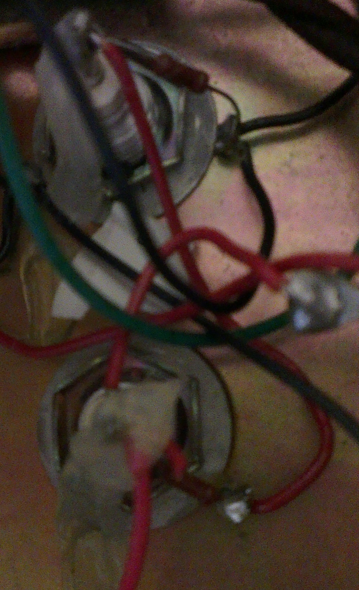
Had a crack at trying to figure out what old mate did in the photo above. It looks like he sent the black wire coming from the tranny (previously one of the three that went to the weird ground terminal of the big filter cap) to the -ve terminal of the cap that replaced it, which then seems to be jumpered by a wire (maybe a resistor) to the a clamp mounting scew; the black from the board (the second of the three) to chassis ground at the screw that mounts the cap's clamp (hard to tell from that photo), and the black from the 4ohm tap (the third) I can't really tell, potentially it looks as though it goes to chassis ground on the other filter cap's clamp mount . I have no idea what happened to the lead coming from p7 of v5 that went to that caps -ve and then to ground. It may be directly going to ground.
This photo is really crap.
Could anyone compare the pic and my guesswork to the schematic and tell me what the frig is going on here?
I'd really like to play again.
Thanks.
Undid some known mistakes, possibly created more (cold solder for the win), just want to get it to the point where it fires up and makes noise without tripping out.
Had a crack at trying to figure out what old mate did in the photo above. It looks like he sent the black wire coming from the tranny (previously one of the three that went to the weird ground terminal of the big filter cap) to the -ve terminal of the cap that replaced it, which then seems to be jumpered by a wire (maybe a resistor) to the a clamp mounting scew; the black from the board (the second of the three) to chassis ground at the screw that mounts the cap's clamp (hard to tell from that photo), and the black from the 4ohm tap (the third) I can't really tell, potentially it looks as though it goes to chassis ground on the other filter cap's clamp mount
. I have no idea what happened to the lead coming from p7 of v5 that went to that caps -ve and then to ground. It may be directly going to ground.This photo is really crap.
Could anyone compare the pic and my guesswork to the schematic and tell me what the frig is going on here?
I'd really like to play again.
Thanks.
WWPD?
fcknoise wrote:You are all fucking tryhard effort posting nerds
Invisible Man wrote:I'm probably the most humble person I know. I feel good about smelling my own butthole.
Jesus Was a Robot wrote:Did you just assume Billy Corgan's dildo preference??
-
Iommic Pope
- IAMILFFAMOUS
- Posts: 11405
- Joined: Tue Mar 05, 2013 8:41 pm
- Location: Frimmin' on the Fram
31 posts
• Page 2 of 3 • 1, 2, 3
Who is online
Users browsing this forum: No registered users and 16 guests
Sponsored Ad. (Please no inflated/repetitive clicking. Thanks!) 
|